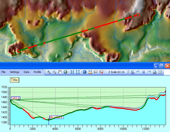
With the tool the user drags a line on the View. The start point of the line defines the position of the Observer. The visibility is calculated for the data points along the line. The results are displayed:
- On the View - a group graphic with color coded visible and invisible portions of the line
- In the Profile Window - the line of sight is drawn together with the profile of the surface which gives the user better understanding of the results. The user has option to display also the Break Lines - LOS for which the visibility changes
The Draw Visibility Observer tool
![]() allows the user to move the
Observer location by clicking on the Map.
allows the user to move the
Observer location by clicking on the Map.
The Draw Visibility Target tool
![]() allows the user to move the Target
location by clicking on the Map.
allows the user to move the Target
location by clicking on the Map.
Whenever the Observer or Target locations are changed a new Line of sight is calculated and displayed.
LOS Settings
The settings for the Line of Sight can be adjusted from the Line of Sight Settings dialog (Settings Menu ==> Line of Sight Settings).
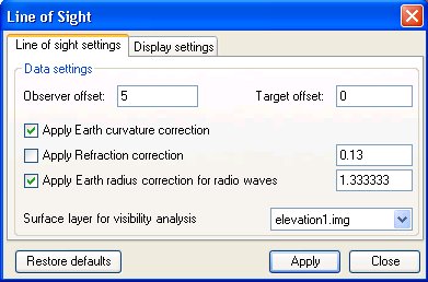 |
On the Line of
sight settings tab the
user can change the following parameters:
|
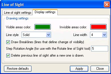 |
On the
Display settings tab the
user can change the following parameters:
|
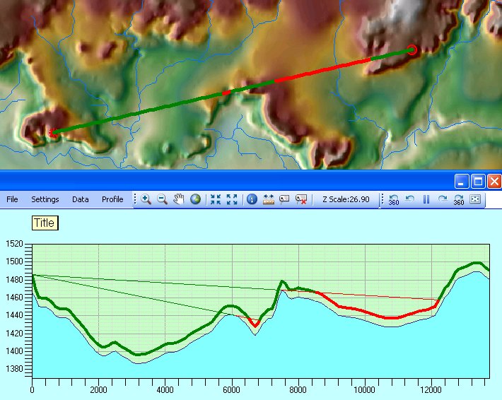
EXAMPLE:
| Observer and Target offset applied |
 |
| See examples for applying Earth Curvature, Light and Radio Waves refractions here |
Copyright © Ianko Tchoukanski