Inputs:
- A feature layer (Points, Polylines, Polygons). Although shapes from all types can be used, the interpolation method is best suited for scattered data points.
- Output raster name and format
- Cell Size of the output raster
- Value field - a field from the attribute table to be used as a source for the values of the raster. If the input is of PointZ or PolylineZ type, the Z values of the features can be used as source for the raster values
- Power - A positive number that defines the weight of the distance in the interpolation process. The weight of each known point decreases as the distance from it to the interpolated cell increases. The higher the value of the Power, the faster the weight of the known point decreases. If the Power is less than 1 the appearance of the resulting surface will be sharper. If the value of the Power is greater than 1 the appearance of the surface will be smoother. Very large values of the Power will result of a surface with only few known points influencing the value of the interpolated cell. The most commonly used value is 2 (default)
- Number of sources - the number of known points to be used in the interpolation of the value of each cell. The default value is 12.
- Cut off distance (optional) - a known point will not influence the interpolation of cells that are farther than this distance from the point.
Output:
- A floating point raster.
Examples:
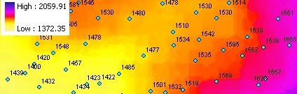 |
Power = 0.5 |
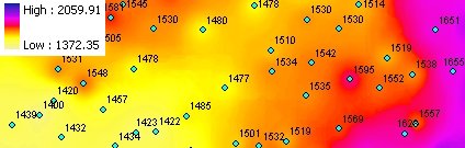 |
Power = 2 |
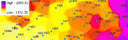 |
Power = 15 |
Notes:
- Initially the name of the output raster
defines the raster format
- no extension specified - ESRI binary GRID
- .img extension (for example raster1.img) - ERDAS IMAGINE image.
- .tif extension (for example raster1.tif - Tagged Image File Format (TIFF) image.
- The initial output raster format can be changed by selecting the desired output in the dialog.
- Currently only file based rasters are supported. Rasters cannot be stored in a GeoDatabase. After you get the desired result, you can export the raster to a GeoDatabase using the standard ArcGIS tools.
- The feature class must be in a projected coordinate system
Command line syntax
ETS_GPIDW <Input Dataset> <Out Raster> <Elevation Field> < Cell Size> <Power> <Number of Sources> {Cutoff Distance}
Parameters
| Expression | Explanation |
|---|---|
| <Input Dataset> | A Point, Polyline or Polygon layer or feature class |
| <Out Raster> | A String - the full name of the output raster (A raster with the same full name should not exist). The output raster type depends on the extension of the output file(see Notes above) |
| <Elevation Field> | A String representing the name of the field which values are going to be used for interpolation. |
| <Cell Size> | A Double representing the cell size of the output raster. |
| <Power> | A Number - see main description above |
| <Number of Sources> | A Number - see description above |
| {Cutoff Distance} | A Double representing the Cutoff distance. |
Scripting syntax
ETS_GPIDW (Input Dataset, Out Raster, Elevation Field, Cell Size, Power, Number of Sources ,Cutoff Distance)
See the explanations above:
<> - required parameter
{} - optional parameter
All ESRI
products mentioned are trademarks of Environmental Systems Research
Institute, Inc.
Copyright: Ianko Tchoukanski